设计文档综述
数据通路设计
数据通路和实验指导书相仿。
顶层模块主要包含 $5$ 级流水线模块和额外的一个转发控制器。
如下图所示: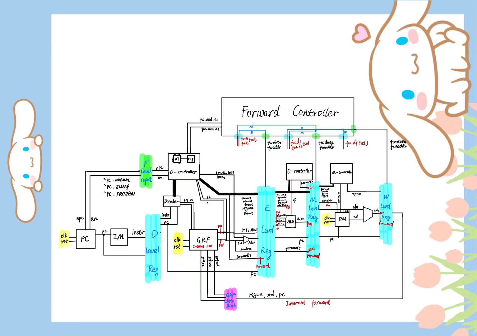
模块文件结构
大致结构是3层,第一层是顶层模块,用于桥接各级流水线;第二层是各级流水线,以及独立于流水线的转发控制模块;第三层是各个零碎的部件。各级流水线寄存器都位于同名流水线内部。如 D 级流水线寄存器在 Decode 模块内。

第二层模块概述
Fetch
模块声明:
module Fetch(
    input         clk,
    input         reset,
    input  [31:0] F_npc,
    input  [1 :0] F_pcen,
    output [31:0] D_instr,
    output [31:0] D_pc
);
端口定义如下: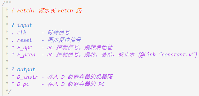
包含的子模块:
- IM
Decode
模块声明:
module Decode(
    // global
    input          clk,
    input          reset,
    // exchange with Fetch
    output [31: 0] F_npc,
    output [1 : 0] F_pcen,
    // get register in
    input  [31: 0] D_instr_in,
    input  [31: 0] D_pc_in,
    // exchange with Writeback
    input  [31: 0] writeback_grf_wd,
    input  [4 : 0] writeback_grf_wa,
    input  [31: 0] writeback_grf_pc,
    // exchange with forward controller
    output [4 : 0] fw_need_a1,
    output [4 : 0] fw_need_a2,
    input  [31: 0] fw_need_d1,
    input  [31: 0] fw_need_d2,
    input          fw_need_sel1,
    input          fw_need_sel2,
    // to next level's register
    output [4 : 0] E_fw_write_a,
    output [31: 0] E_fw_write_d,
    output [31: 0] E_pc,
    output [31: 0] E_alu_1,
    output [31: 0] E_alu_2,
    output [2 : 0] E_mips_format,
    output [5 : 0] E_mips_opcode,
    output [5 : 0] E_mips_funct,
    output [4 : 0] E_mips_reg_wa,
    output [4 : 0] E_mips_shamt,
    output [31: 0] E_memdata
);
端口定义如下: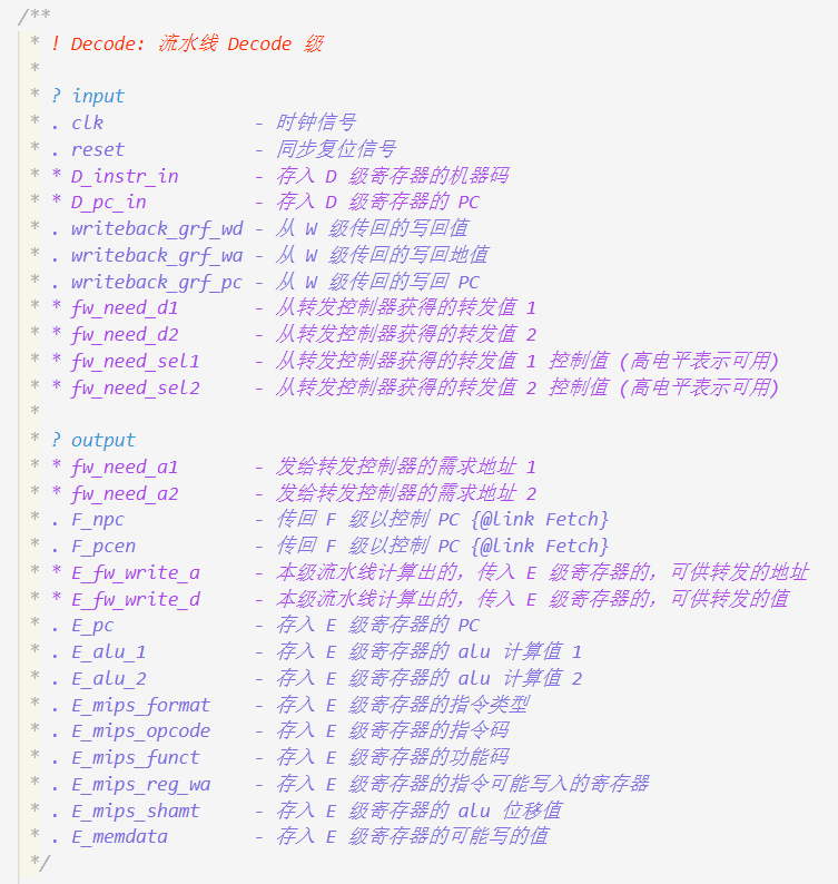
包含的子模块:
- D_Controller
- Decoder
- GRF
- MUX_2 (3)
- RegisterFrozen (2)
Execute
模块声明:
module Execute(
    // global
    input          clk,
    input          reset,
    // get register in
    input  [4 : 0] E_fw_write_a_in,
    input  [31: 0] E_fw_write_d_in,
    input  [31: 0] E_pc_in,
    input  [31: 0] E_alu_1_in,
    input  [31: 0] E_alu_2_in,
    input  [2 : 0] E_mips_format_in,
    input  [5 : 0] E_mips_opcode_in,
    input  [5 : 0] E_mips_funct_in,
    input  [4 : 0] E_mips_reg_wa_in,
    input  [4 : 0] E_mips_shamt_in,
    input  [31: 0] E_memdata_in,
    // exchange with forward controller
    input  [31: 0] fw_need_d1,
    input  [31: 0] fw_need_d2,
    input          fw_need_sel1,
    input          fw_need_sel2,
    // notice forward controller
    output [4 : 0] E_fw_write_a_out,
    output [31: 0] E_fw_write_d_out,
    // to next level's register
    output [4 : 0] M_fw_write_a,
    output [31: 0] M_fw_write_d,
    output [2 : 0] M_mips_format,
    output [5 : 0] M_mips_opcode,
    output [5 : 0] M_mips_funct,
    output [4 : 0] M_mips_reg_wa,
    output [31: 0] M_pc,
    output [31: 0] M_alu_out,
    output [31: 0] M_memdata
);
端口定义如下: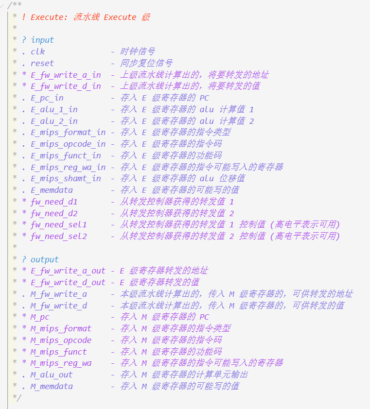
包含的子模块:
- ALU
- E_Controller
- MUX_2 (5)
- Register (11)
Memory
模块声明:
module Memory(
    // global
    input          clk,
    input          reset,
    // get register in
    input  [4 : 0] M_fw_write_a_in,
    input  [31: 0] M_fw_write_d_in,
    input  [2 : 0] M_mips_format_in,
    input  [5 : 0] M_mips_opcode_in,
    input  [5 : 0] M_mips_funct_in,
    input  [4 : 0] M_mips_reg_wa_in,
    input  [31: 0] M_pc_in,
    input  [31: 0] M_alu_out_in,
    input  [31: 0] M_memdata_in,
    // exchange with forward controller
    input  [31: 0] fw_need_d,
    input          fw_need_sel,
    // notice forward controller
    output [4 : 0] M_fw_write_a_out,
    output [31: 0] M_fw_write_d_out,
    // to next level's register
    output [4 : 0] W_fw_write_a,
    output [31: 0] W_fw_write_d,
    output [31: 0] W_pc
);
端口定义如下: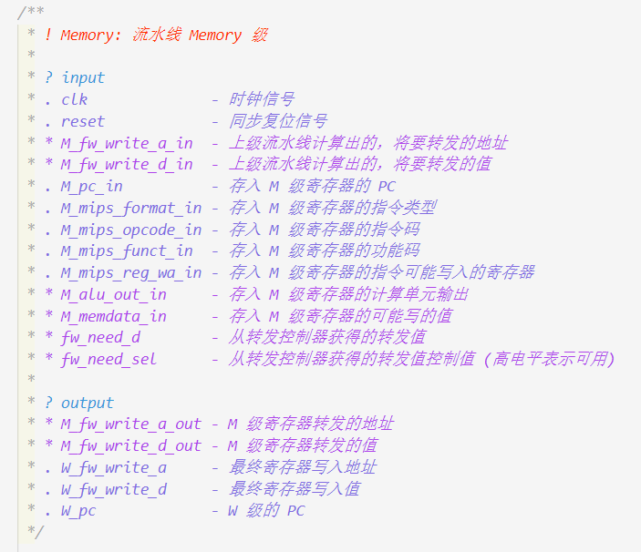
包含的子模块:
- DM
- MUX_2 (3)
- M_Controller
- Register (9)
Writeback
模块声明:
module Writeback(
    // global
    input          clk,
    input          reset,
    // get register in
    input  [4 : 0] W_fw_write_a_in,
    input  [31: 0] W_fw_write_d_in,
    input  [31: 0] W_pc_in,
    // notice forward controller
    output [4 : 0] W_fw_write_a_out,
    output [31: 0] W_fw_write_d_out,
    // exchange with Register Files
    output [4 : 0] writeback_grf_wa,
    output [31: 0] writeback_grf_wd,
    output [31: 0] writeback_grf_pc
);
端口定义如下: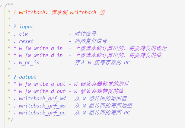
包含的子模块:
- Register (3)
ForWardController
模块声明:
module ForwardController(
    input         clk,
    input         reset,
    input  [4: 0] D_fw_need_a1,
    input  [4: 0] D_fw_need_a2,
    input  [4: 0] E_fw_write_a,
    input  [31:0] E_fw_write_d,
    input  [4: 0] M_fw_write_a,
    input  [31:0] M_fw_write_d,
    input  [4: 0] W_fw_write_a,
    input  [31:0] W_fw_write_d,
    output reg    D_fw_need_sel1,
    output reg [31:0] D_fw_need_d1,
    output reg    D_fw_need_sel2,
    output reg [31:0] D_fw_need_d2,
    output reg    E_fw_need_sel1,
    output reg [31:0] E_fw_need_d1,
    output reg    E_fw_need_sel2,
    output reg [31:0] E_fw_need_d2,
    output reg    M_fw_need_sel,
    output reg [31:0] M_fw_need_d
);
端口定义如下: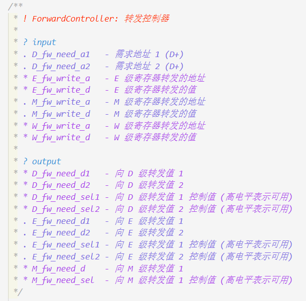
包含的子模块:
- Register (3)
思考题
我们使用提前分支判断的方法尽早产生结果来减少因不确定而带来的开销,但实际上这种方法并非总能提高效率,请从流水线冒险的角度思考其原因并给出一个指令序列的例子。
当分支判断需要使用的值还未算出时,分支指令会被直接阻塞在 D 级,
这可能导致分支指令被阻塞多个周期。然而其实此时让分支指令流水一个周期,
使得延迟槽内的指令能够进行译码,这将能达到更快的速度。例如:
lw $ra 0($0)
jr $ra
lui $s0 0xffff
因为延迟槽的存在,对于 jal 等需要将指令地址写入寄存器的指令,要写回 PC + 8,请思考为什么这样设计?
因为
jal的延迟槽内的指令已经紧跟着jal指令运行了,
而不需要在返回的时候再次运行。我们要求所有转发数据都来源于流水寄存器而不能是功能部件(如 DM、ALU),请思考为什么?
直接转发自功能部件会导致数据通路变长,因此运行效率降低。另外也可能产生毛刺效应。
我们为什么要使用 GPR 内部转发?该如何实现?
实现内部转发可以减少一级流水线寄存器带来的消耗。
实现方案是,如果检测到寄存器写地址和读地址相同且非0,
就可以直接把读取值改为将要写入的值我们转发时数据的需求者和供给者可能来源于哪些位置?共有哪些转发数据通路?
有以下转发通路:
- $E \rightarrow D$
- $M \rightarrow D$
- $M \rightarrow E$
- $W \rightarrow E$
- $W \rightarrow M$
在课上测试时,我们需要你现场实现新的指令,对于这些新的指令,你可能需要在原有的数据通路上做哪些扩展或修改?提示:你可以对指令进行分类,思考每一类指令可能修改或扩展哪些位置。
目前来说,我需要更改以下模块:
- 集中式译码器,添加新指令的译码规则;
- AT 模块,评估转发或阻塞;
- 根据不同的指令修改它要执行的流水线级控制器
对于跳转指令,修改 D 级
对于计算指令,修改 E 级
对于储存指令,修改 M 级
简要描述你的译码器架构,并思考该架构的优势以及不足。
我采用了集中式译码器。优势是,只在 D 级译码,
其他流水级都不需要知道整个指令的机器码,
只要知道指令是什么,要用的值和要写的地址就可以了。
缺点是,每级流水线寄存器需要存储的值的个数增加。

